Autodesk Fusion 360 is awesome, it’s one of my favourite pieces of software. This guide will step you through the process of taking a finished model, generating a tool path and exporting it as g-code. Making the output compatible with GRBL controllers in cheap CNC machines like generic 2418 mills you can get from China.
Step #1
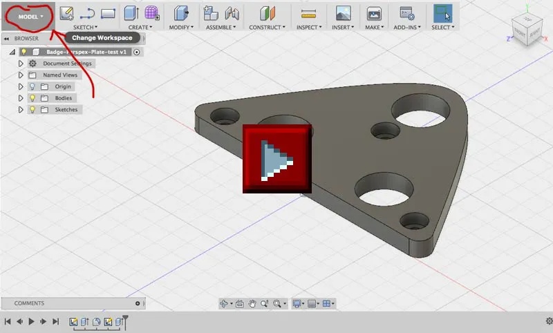
Open the file you want milled (you can download the example I am using here) and switch to the ‘CAM’ workspace. This switches us over to Fusion’s computer aided manufacturing functionality for generating CNC toolpaths.
Step #2
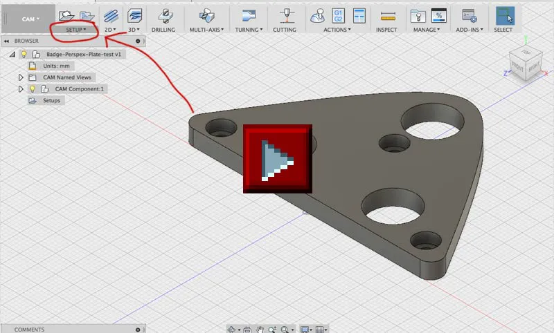
A setup holds general properties about the milling job. It lets us tell Fusion a few details about the stock, or the material we will be using to cut the part from. Most importantly, it lets us setup how our stock will be orientated in our mill. We need to set the coordinate system such that the Z-axis points up, while the x and y-axis from the a plane matching the top of the stock (the yellow semi-transparent box).
- Select the ‘SETUP’ menu
- Press ‘New Setup’.
- In the Setup tab, select the orientation drop down and click ‘Select Z axis/plane & X axis’.
- Select the axis we want to use for Z, in the pictured example, the green axis is used.
- Select ‘Box Point’ to select a stock point to be the origin for our job.
- Click one of the points on the top of the yellow semi-transparent stock box.
- Select the Stock tab
- Bump the side offset up by to 5mm, to give us a bit of a margin when cutting the part. Set the top offset to 0mm (assuming we will be cutting this from material that is the same thickness as the part) and press OK.
Step #3
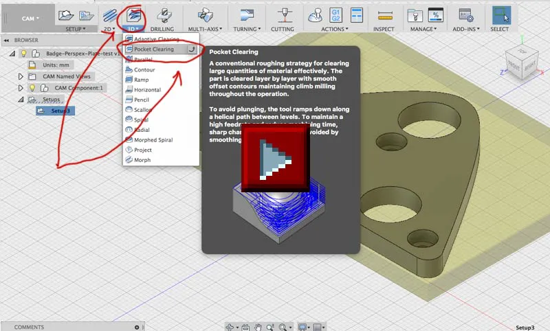
Now we are ready to start giving actions for our CNC mill to perform. The first is to clear out all the holes in the piece, some of these are countersunk, so we will use ‘pocket clearing’ for this.
- Select the ‘3D’ menu and press ‘Pocket Clearing’.
- Press the ‘Select…’ button next to tool.
- Create a new tool using the buttons in the top right of the select tool dialog.
- Select the cutter tab and fill out all the details for the milling bit you are going to use. I used a set of digital calipers to make all the measurements. The only that might not be obvious is ‘Number of flutes’, a flute is the channel in the side of the bit. Those helical troughs that spiral up the side. My tool had two. Press OK when finished entering in the details.
- Select your freshly created tool and press OK.
- Set the feedrates for the operation, I dial these way back to 100mm/min for my little mill on acrylic. It’s too easy to break the tool otherwise.
- Select the geometry tab, and change the ‘Matching Boundary’ to Silhouette. Press OK.
Step #4
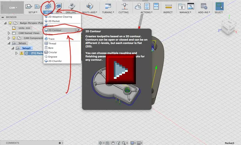
The next operation for our mill is to cut the whole part out from the stock. Our shape is just a flat 2D part, so we can use a 2D contour for this.
- Select the ‘2D’ menu and press ‘2D contour’.
- Fusion should remember the tool selection and feedrates, so nothing to change in the tool tab.
- Select the geometry tab, click the button to the right of contour selection and select the BOTTOM edge of the part. If you select the top, you will only make a scratch in the top of the stock and won’t cut the part out completely.
- Select Tabs, these little things hold the part in place while milling to stop it flying away and getting damaged right at the end of the job. They are pretty easy to break away and sand off at the end.
- Select Passes and enable multiple depths. For my little 2418 mill, I can’t really take away more than a 1mm of acrylic each pass. Press OK.
Step #5
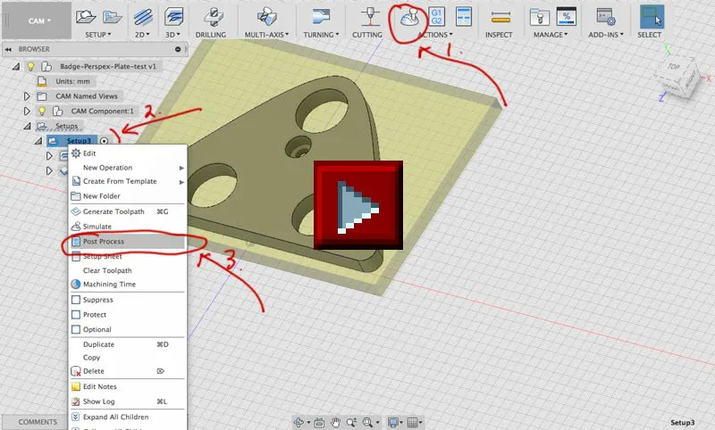
Now that our toolpath is all defined, we can run a simulation in Fusion. It’s the button with an icon that looks a little joystick button in the top menu. I turn the stock on so I can see fusion digitally carving away on the part. After you are happy that everything is working correctly, we can export the g-code:
- Right click on your setup and select post-process.
- Select ‘GRBL’ from the post processor drop down.
- Press OK and tell fusion the filename for your gcode file. After Fusion has finished writing the file, you will be presented with an editing window filled with the completed g-code. You can close this if you don’t have any changes you want to make by hand.
That’s it, now you have a g-code file that can be loaded up in chillipeppr or whatever else you are using to send commands to your GRBL powered CNC mill.
Hi! Subconsciously you already know this, but let's make it obvious. Hopefully this article was helpful. You might also find yourself following a link to Amazon to learn more about parts or equipment. If you end up placing an order, I make a couple of dollarydoos. We aren't talking a rapper lifestyle of supercars and yachts, but it does help pay for the stuff you see here. So to everyone that supports this place - thank you.