For about $320AUD you can get a CNC milling machine delivered in kit-form. I’m going to use mine for etching circuit board prototypes, and maybe cutting a bit of acrylic. It also came with a 500mw laser and safety glasses, but I will be sticking with milling for now.
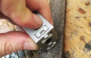
#1: Use a file to tidy up the cast aluminium parts, removing any rough edges left by the casting processes.
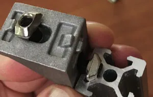
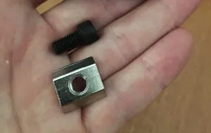
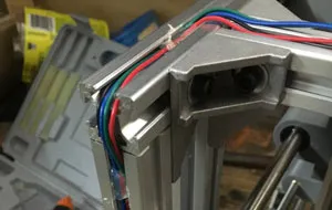
#2: Add one of the smaller cap head screws, washers and t-slot nuts to each side of a right-angle connector. These t-slot nuts slide into the extruded profiles and tightened in position.
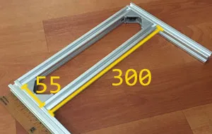
#3: Take two 300mm lengths of extruded aluminium and the two 220mm lengths. Attach with right angle connectors into a boxy 'A' shape, with the crossbars separated by 55mm.
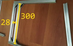
#4: Take the two 330mm lengths of extruded aluminium and attach two 300mm lengths. This time, separating the crossbars by 28mm. You will need to tighten the top crossbar in place before positioning the lower.
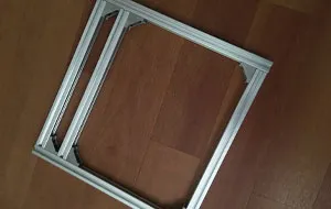
#5: Take the last 300mm length of extruded aluminium and use it to enclose the base.
#6: Using six of the right-angle connectors, attach the two assemblies to make an L shape. With the upright intersecting the base at the middle crossbar. Double check to make sure everything is square and true, and ensure your connectors are well tightened.
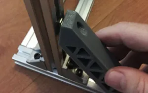
#7: Using more of the smaller cap head screws and t-slot nuts, add the 3D-printed struts to further reinforce the L shape. The t-slot nut will slide into the channel, just ensure it has rotated 90 degrees when tightened in place. Be careful not to over-tighten the screws here as you can crack the 3D-printed part.
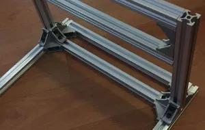
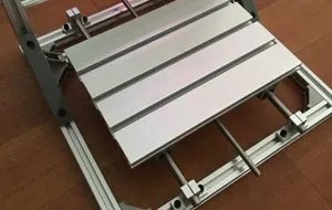
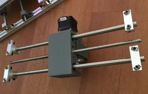
#8: During construction of the build platform, use the larger cap head screws and t-slot nuts to attach components.
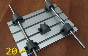
#9: Attach the linear bearings 20mm from the edge of the build platform. Use two of the 330mm smooth rods to help get everything aligned. Spend a bit of time here to get things as precise as you can, it will help ensure that the platform can slides smoothly. Again, be careful not to over-tighten and crack the 3D-printed parts.
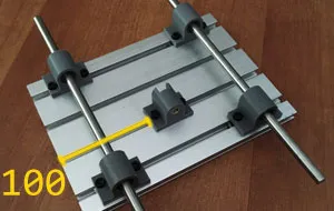
#10: Attach the nut-mount to the build platform, 100mm from the edge.
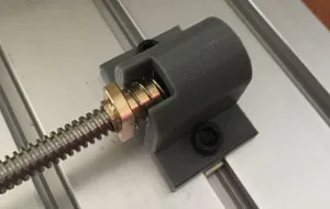
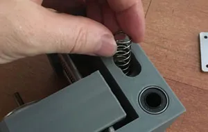
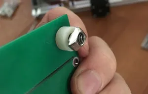
#11: Insert one of the springs into the nut mount. Thread the screw into the ball nut, compressing the spring till the nut flange sits flush with the nut-mount. Thread the screw into the nut-mount to hold everything in place.
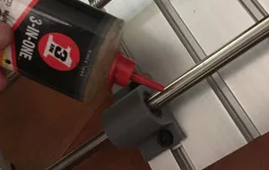
#12: Drop a couple of dots of fine machine oil on the smooth rods, and ensure everything moves fluidly.
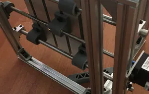
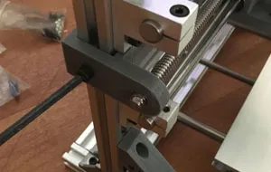
#13: Using the brackets and smaller t-slot nuts, attach the build platform to the base of the frame. Take care to ensure that the round rods are parallel and that the platform moves freely.
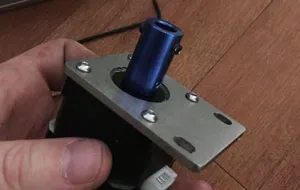
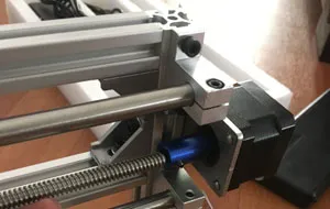
#14: Using the smallest screws, attach a stepper motor to the steel mount and attach the blue coupling.
#15: Using smaller t-slot nuts and screws, attach the stepper motor and idler bearing to the base of the frame. I found it easier to flip the mill on its side to get a good alignment.
#16: Add a spring to the 3D printed z-axis assembly and thread the screw and ball nut into position.
#17: Add 340mm smooth rod, position mounts, adding screws and t-slot nuts.
#19: Assemble the second stepper motor mount and attach to the mill gantry.
#20: Fit the idler bearing and ensure that all fittings have been been correctly tightened.
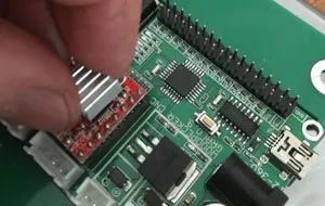
#21: Add the small aluminium heatsinks to the stepper drivers.
#22: Add cap-screws, small plastic grommets and t-slot nuts to the control board.
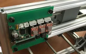
#23: Mount the control board to the mill gantry.
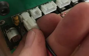
#24: Wire the spindle motor down to the control board.
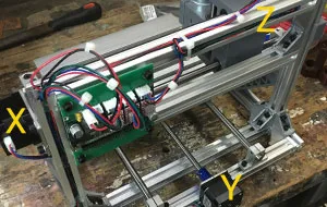
#25: Wire the stepper motors down to the control board, the one on the spindle mount gets routed to the Z-channel. The motor on the gantry get routed down to the X-channel. The motor on the base of the mill gets routed over to the Y-channel.
#26: Using hot glue and cable ties, organise the wiring down the channels of the extruded aluminium profiles.
Hi! Subconsciously you already know this, but let's make it obvious. Hopefully this article was helpful. You might also find yourself following a link to Amazon to learn more about parts or equipment. If you end up placing an order, I make a couple of dollarydoos. We aren't talking a rapper lifestyle of supercars and yachts, but it does help pay for the stuff you see here. So to everyone that supports this place - thank you.