Stepper motors are ideal for 3D printers, robots, mills and lathes; you can program them to rotate by very precise amounts. Push the right signal (“I will have 36 degrees please”) into the motor driver and it will spin or ‘step’ by the nominated amount.
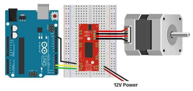
Wait! I know I just said signal, but this won’t devolve into a mind melting Fourier Transform nightmare, I promise. In fact, drivers such as the ‘EasyDriver’ by Sparkfun, or the ‘A4988’ by Pololu have a step pin that can be wired to a digital pin on an Arduino. This pin can be used to ‘twitch’ a stepper motor by single steps. Just set the pin to high, and your stepper motor will rotate by either 1.8 or 0.9 degrees (depending on the step size of your stepper motor).

The code for this is pretty straight forward:
    #define STEP_PIN 3

    void setup() {
      pinMode(STEP_PIN, OUTPUT);
      digitalWrite(STEP_PIN, HIGH);
    }

    void loop() {
    }
To smoothly drive a stepper motor, just set the pin high, wait a little while, set it back low again and repeat, like so:
    #define STEP_PIN 3

    void setup() {
        pinMode(STEP_PIN, OUTPUT);
    }

    void step(long stepDelay) {
        digitalWrite(STEP_PIN, HIGH);
        delayMicroseconds(stepDelay);
        digitalWrite(STEP_PIN, LOW);
        delayMicroseconds(stepDelay);
    }

    void loop() {
        // rotate by 100 steps.
        for (int i = 0; i < 100; i++) {
            step(200);
        }
    }
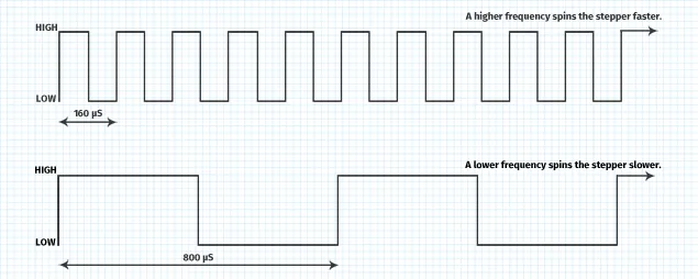
By the way, you just generated a signal - a 6.25Khz square wave. It looks like this:

To spin the motor faster, just decrease the delay between the high and low pulse, i.e. change step(200) to step(80). This increases the frequency of the square wave and the driver spins the motor faster. To spin the stepper motor slower, just increase the delay between the high and low pulse, i.e. change step(200) to step(400). This decreases the frequency and the driver spins the motor slower.

The problem with the example code above is that it blocks - your Arduino can’t do anything else while it is generating the signal for the stepper driver. You have to wait till the motor has rotated by the desired amount, before your Arduino is free to do something else. This is usually fine for small movements, but can be a bigger problem over longer distances.
I ran into this longer distance problem when building a robotic control system for an artwork that Keith Armstrong was creating. The piece features a linear rail (a few metres long) and a drive system powered by a stepper motor allowing the robot to crawl from one end to the other. It takes a few minutes for the robot to complete its end-to-end journey and all the while, it needed to be doing things in between.

For my first attempt at non-blocking stepper control, I shifted the step control directly into the Arduino loop, and wrapped it with some checks to see if we had gotten to our desired location. I also did the other things that needed to get done in the same main loop, a little bit like this:
    #define STEP_PIN 3

    void setup() {
        pinMode(STEP_PIN, OUTPUT);
    }

    void step(long stepDelay) {
        digitalWrite(STEP_PIN, HIGH);
        delayMicroseconds(stepDelay);
        digitalWrite(STEP_PIN, LOW);
        delayMicroseconds(stepDelay);
    }

    void loop() {
        DoOtherStuff();

        if (!thereYet()) {
            step(200);
        }
    }
It was a clunky disaster. The motor rattled and drove very poorly. The problem was that ‘DoOtherStuff’ took a variable amount of time to complete. Sometimes it would take 183 microseconds, sometimes 191. It doesn’t sound (or look) like a lot, but those subtle timing differences resulted in a noisy square wave (see below), which was enough to make the motor rattle.

The trick to solving this problem was to ‘hide’ the computation of the other stuff in part of the wave. Rather than just calling delayMicroseconds and wasting ATMega cycles, I put them to good use executing ‘DoOtherStuff’. I then added some padding to ensure that the low of the wave was a consistent length each time.
    #define STEP_PIN 3

    unsigned long t = 0;

    void setup() {
        pinMode(STEP_PIN, OUTPUT);
    }

    void step(long stepDelay) {
        digitalWrite(STEP_PIN, HIGH);
        delayMicroseconds(stepDelay);
        digitalWrite(STEP_PIN, LOW);

        unsigned long dt = micros() - t;
        if (dt < STEP_DELAY_SHOW) {
          delayMicroseconds(STEP_DELAY_SHOW - dt);
        }

        t = micros();
    }

    void loop() {
        DoOtherStuff();

        if (!thereYet()) {
            step(200);
        }
    }

The only downside was that this imposed a limit to how fast the motor could be driven. The time it took for ‘DoOtherStuff’ to perform had to ‘fit’ in the square wave, meaning the frequency couldn’t be higher than that required by the computation.
The end result was a much smoother drive for the stepper motor, and an Arduino sketch that could also do other things at the same time.
The full example of non-blocking stepper control can be found on Github.
EDIT: Also found an post on driving stepper motors directly from a Raspberry Pi. It would be interesting to see how it compares with the Arduino.
Comments:
You can join the conversation on Twitter or Instagram
Become a Patreon to get early and behind-the-scenes access along with email notifications for each new post.
Hi! Subconsciously you already know this, but let's make it obvious. Hopefully this article was helpful. You might also find yourself following a link to Amazon to learn more about parts or equipment. If you end up placing an order, I make a couple of dollarydoos. We aren't talking a rapper lifestyle of supercars and yachts, but it does help pay for the stuff you see here. So to everyone that supports this place - thank you.
